

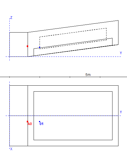
Before we begin our work it is worthwhile to consider if our room does not have any characteristics that might make creation of the model easier (decreasing the number of points we have to implement by hand in particular). In our example it is symmetrical, so we only have to draw half of it – CATT-Acoustic has a MIRROR function, that creates a reflexion and copies the points in regard to the Y axis. On the projections above the points’ numeration has been marked – it is prudent to mark them counter-clockwise – that way the plane, that we will create on them will be facing the interior of the model with its reflexive side. Having all that data there is not much to do but to open the afore-created MASTER.GEO file located in the project’s folder and begin placing the points.
In the CORNERS section we add, following the id x y z syntax:
id – point’s number
x, y, z – consecutive values in a chosen coordinate system
1 5 0 0

2 5 3 0

3 5 18 2

4 0 18 2

5 0 3 0

6 0 0 0
We have defined first six points that make the floor, but after clicking the Save and Run button in View and check model section in the Modeling window,responsible for the behavior and re-drawing the geometry’s model an error occurs. The model does not work without creating the plane. To do so, in PLANES section we write, following the syntax [id name / / absname ]:
id – plane’s number
name – plane’s name
absname – defined material in which the plane is covered
(podloga means floor in Polish, parkiet means parquet in Polish – the original names used for the sake of the afore-created exemplary files)
[1 podloga /1 2 5 6/ parkiet]
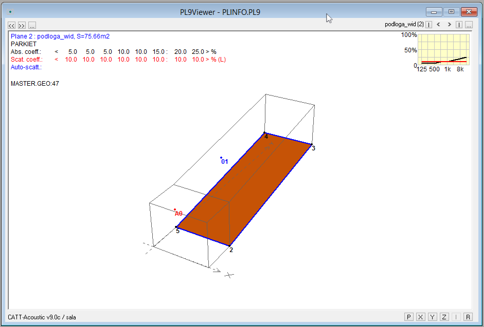
[2 podloga_wid /2 3 4 5/ parkiet]
When the point’s numbers are in a sequence we can also write:
[2 podloga_wid /2-5/ parkiet]
Above we have created 2 planes – the floor at the bottom of the room and a slanted part of the audience. The points, in agreement with the rule shown above, are listed in a counter-clockwise order. On every plane a predefined material must be placed – we have used the one called parkiet on the floor. Now all that is left is to give the properties of absorption and reflection of sound of our parkiet. The syntax of the required command given by the CATT-Acoustic programmers in the commented located (IMPORTANT) over the CORNERS and PLANES sections.
ABS absname <10 10 10 10 10 10> L <10 10 10 10 10 10>
Let us define a material called parkiet with the absorption coefficients in octave bands equal:
| f [Hz] | 125 | 250 | 500 | 1000 | 2000 | 4000 |
| α | 0,05 | 0,05 | 0,05 | 0,1 | 0,1 | 0,15 |
ABS parkiet <5 5 5 10 10 15>
CATT-Acoustic accepts the values given in percentages, but the highest possible value is 99.
We have skipped the numbers before the letter L – those are the sound scattering parameters of the sound s, used while modeling the audience or diffusors with known values of this coefficient. CATT inserts a coefficient equal to 0,1 for each octave by default.
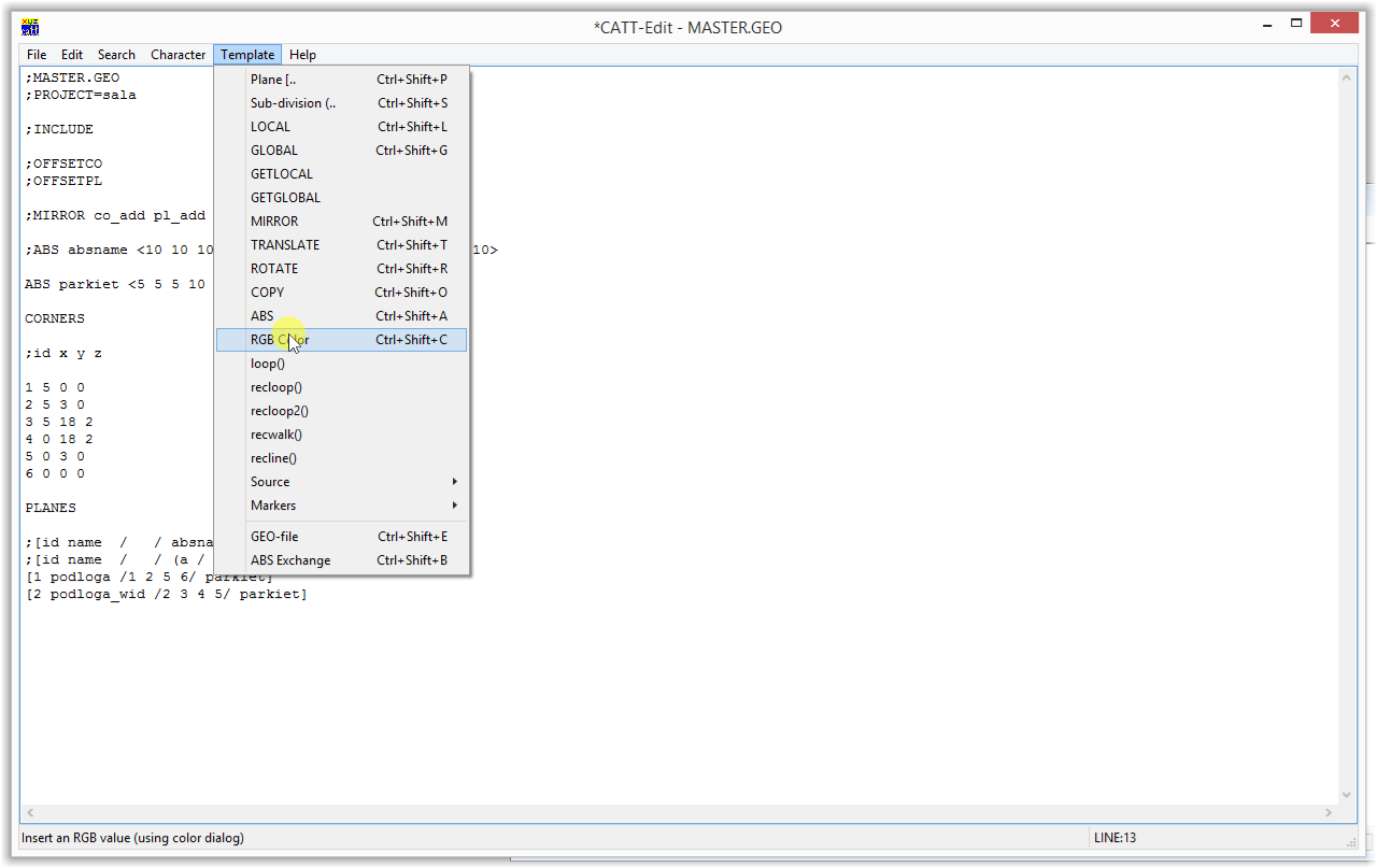
Furthermore, for each material we can choose the color which will be used to mark the planes covered with it in our model. The color, in the RGB standard, must be placed at the end of the line beginning with a command ABS in the braces – I advise to use the color selection tool provide by CATT-Acoustic internal editor, located in the Template section:
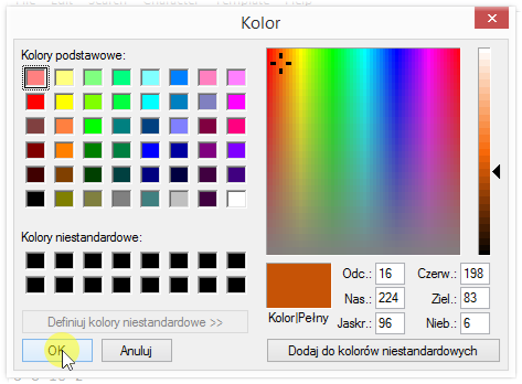
Eventually our material’s definition will take a form:
ABS parkiet <5 5 5 10 10 15> {198 83 6}
We have defined the points, planes and the floor’s material, now we can try turning on the model’s rendering. After pressing the button:
![]()
We get:
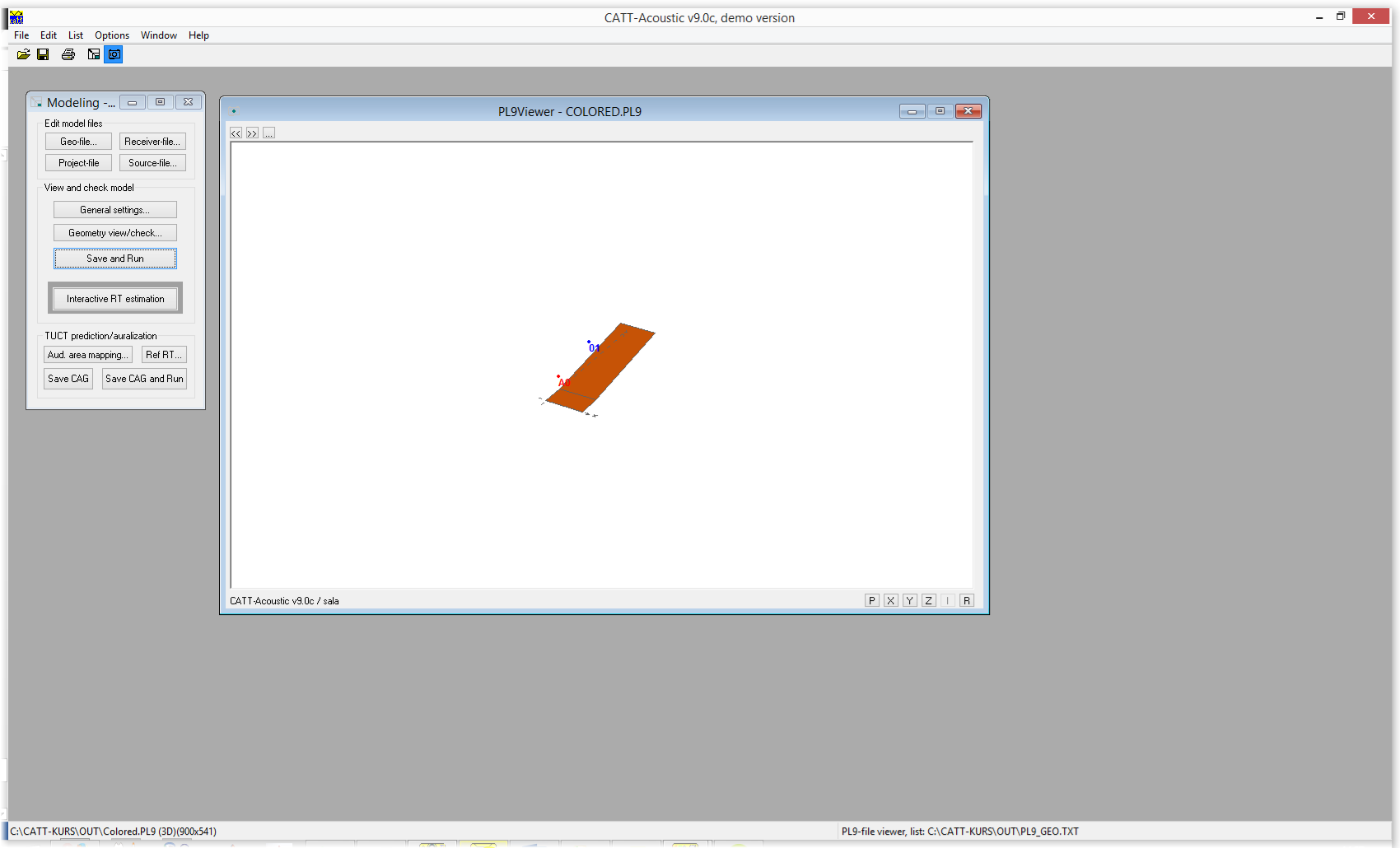
As well as 3D preview window which shows not only the room’s model, but also the spatial distribution of sources and receivers:
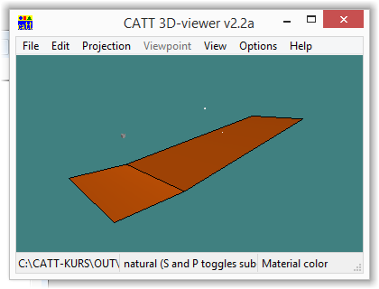
The floor we can see above (more accurately, half of it, but we do not need to worry about it now) is ready. Now we should draw the ceiling and put a correct material on it. It is worth noticing, that the X and Y axis values will repeat themselves, it is only necessary to change the height on which the points are located. To do that let’s cope the already existing points and just change the last value.
11 5 0 4

12 5 3 4

13 5 18 6

14 0 18 6

15 0 3 4

16 0 0 4
We will create the numeration of new points bt adding an identical prefix (in this case – “1”). Thanks to that we will be able to remind ourselves during later stages that they are connected with the floor. Next we define a material that we will place on the ceiling when we finish the plane:
ABS sufit <50 90 99 99 99 95> {226 226 226}
And the aforementioned 2 planes (regions over the podium and audience):
(sufit in ceiling in Polish)
[3 sufitos \11 12 15 16\ sufit]

[4 sufitos \12-15\ sufit]
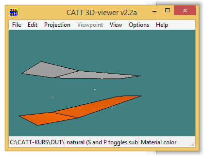
Let’s re-draw the model by using:
The ceiling we have drawn is shown as a transparent contour – it means that it is facing the inside of the model with its active surface. Additionally the results of our actions can be seen on a 3d preview:
To finish our model we also need four walls and a window built into one of them. To define the front, back and side wall located in the front of the room we do not require additional points, the planes can be defined in this very moment:
(sciana means wall and tynk means plaster in Polish)
[5 sciana \1 11 16 6\ tynk]
The sign „\” instead of the „/” we’ve used before is responsible for changing the point succession order – without it the wall would be facing the outside of the model. It is a useful tool that lets us increase the work’s pace in case we make a mistake – there is no need to start writing all the points describing the plane.
[6 sciana \1 2 12 11\ tynk]

[8 sciana /3 13 14 4/ tynk]
And the material called „tynk” (plaster)
ABS tynk <2 2 3 4 4 4> {225 242 104}
To define the last wall we use a command used to place a plane inside a plane. It has a syntax as shown:
[id name / / (a / / a_abs) (b / / b_abs) ]
Where a – plane located inside the main one and b – the main plane (it must be given last).
In our case the plane a is a window, while plane b is a wall with corners in points 2, 3, 13 and 12.
The necessary points will be marked as shown below:
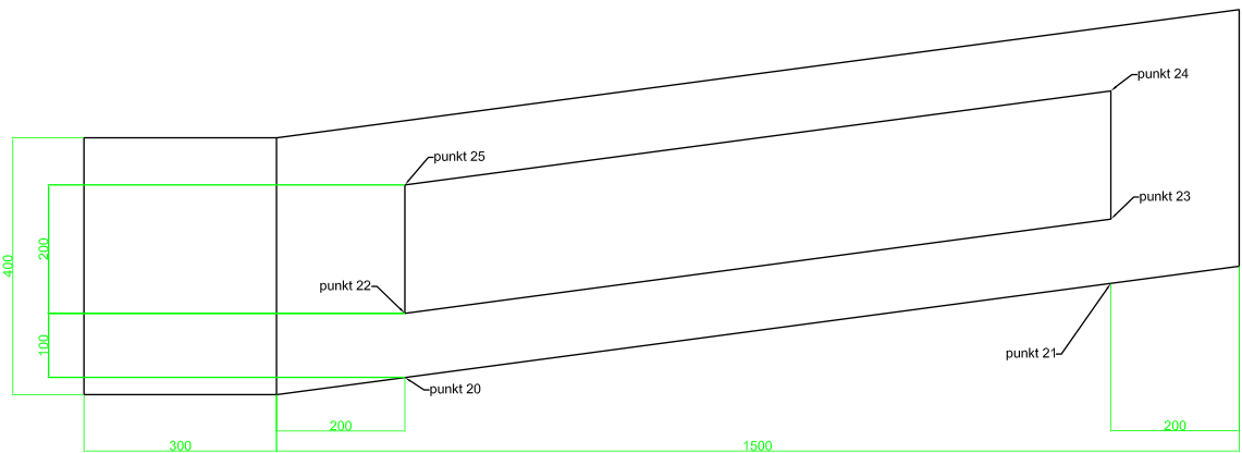
Now we have encountered our first serious problem – in case of points 20 and 21 we can give exact coordinates X and Y, but it might be difficult to give the height they are located on. It might be helpful to use the lock() function. As it’s arguments we give numbers of the 3 points describing the plane among which there is a new (generated right now) point (see graphic below).
New points are defined in a way shown below:
20 5 5 lock(3 4 5)

21 5 16 lock(3 4 5)
A 2 meter high window is located 1 meter over the floor’s surface. CATT-Acoustic allows direct simple mathematical operations on said point as well as recalling its coordinates.
Using this information we can define next 4 points, corners of the window (points 20 and 21 are subsidiary points created before):
22 5 5 z(20)+1

23 5 16 z(21)+1

24 5 16 z(23)+2

25 5 5 z(22)+2
Now we must define a new material: glass
ABS szklo <15 10 5 4 3 2> {96 208 251}
And a wall surface with a window placed inside of it:
[7 sciana \2 3 13 12\(a\22-25\szklo)(b\2 3 13 12\ tynk)]
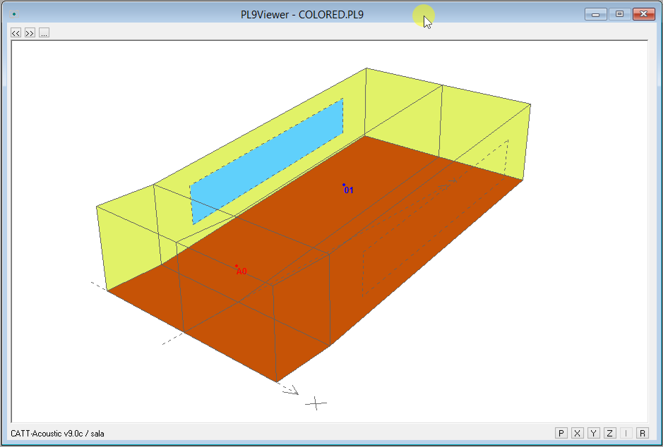
After drawing the model the result of our actions looks like this: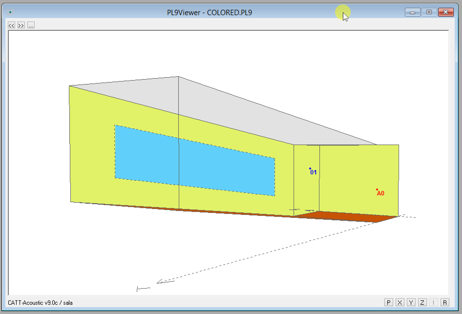
So far we have managed to draw half of our room. To close it we have to “reflect” it in regard to the Y axis – to do this we must use the MIRROR function:
MIRROR co_add pl_add
co_add and pl_add are numbers that we add to individual points and planes – thanks to that we can avoid duplicats in numeration and, eventually – program errors preventing us from generating a model.
To make a mirror image of the planes created so far we place the line:
MIRROR 100 100
Above sections CORNERS and PLANES.
After refreshing the model using
button we can see a complete room:
Now all we have to do is to check if the room is closed:
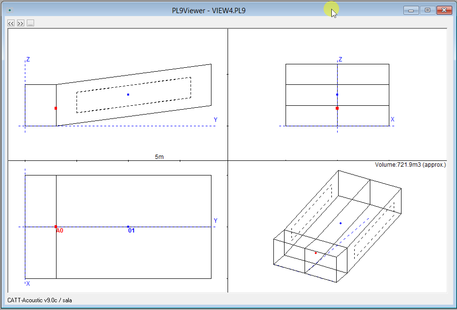
In the bottom right we can see the estimated room’s volume – it indicates that the model has been closed. In the event of forgetting one of the planes or the room not being closed because of leaks a message is displayed telling us that the model is open.
CATT-Acoustic has a built-in tool allowing the user to track the errors disabling us from closing the model. It generates a DEBUG.TXT file in the OUT folder of our simulation. This option can be run by choosing the Create file option in the Debug section of the Geometry view/check window:
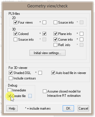
It looks like this:
CATT-Acoustic v9.0c debug : sala
——————————————————————–
DUPLICATE PLANE ID’s : no !
PLANES MODELLED TWICE : no !
DUPLICATE CORNER ID’s : no !
DUPLICATE CORNERS : no !
SINGLE-CONNECTED CORNERS : no !
INACCURATE PLANE CORNERS : no !
COINCIDING PLANES : no !
EDGES CUTTING/TOUCHING : no !
POSSIBLY REVERSED PLANES : no !
——————————————————————–
As we can see no errors were found, but we can once file to be very useful nevertheless.
The errors marked red must be disposed of for the model to work – the others allow it to work, but can also produce unforeseen results.
It is also important that the planes of a very big area should be divided into smaller rectangles of triangles.
 Polski
 English


